3D Printing Application: Hubcap Replacement – Part 2 – Slicing and Printing
Following a previous blog post which focused on the measurement and design of an existing hubcap, this blog post will focus on the Material Selection, slicing, and 3D printing of said hubcap.
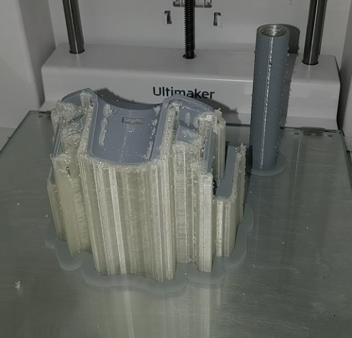
We printed a number of test hubcaps, using ABS for both the build material, and support material. This provided some issues with regards to support structure removal. The main issue that the support presented was that it was very difficult to remove the support in vert intricate areas (such as behind the clip, and in the small slots). This issue led us to the idea that the support structure should be done using a water-soluble material. This way, the finished hubcap can be cleaned of the support by immersing it in water and dissolving the support.
Material Selection
Another issue that was addressed through these test prints was whether or not ABS was the right material for the final print. The materials pool that we had to work with consisted of PET-G, PLA, ABS, PP, PC and Nylons. Based on a selection of material constraints that have been chosen, the right materials will be narrowed down. These constraints are as follows; post-processing ability (spray-ability), compatibility with soluble support materials, and ease of printing.
The ability to be spray painted eliminates PP and Nylons from the pool. The compatibility with soluble support materials eliminates PP too. The ease of printing eliminated PC. This left us with ABS, PLA, and PET-G. However, since we had decided to print using two separate materials, we were restricted to using the dual nozzle printers, like the Ultimaker S3 and S5’s. At the time of printing only PLA and ABS were available and we did not expect PET-G exhibit a significantly better performance. Thus we opted to not test it, although it might also be an ideal candidate due to its reported excellent z-strength. Another viable option might be Tough PLA which has superior toughness when compared to regular PLA and is still quite easy to print.
Material Testing
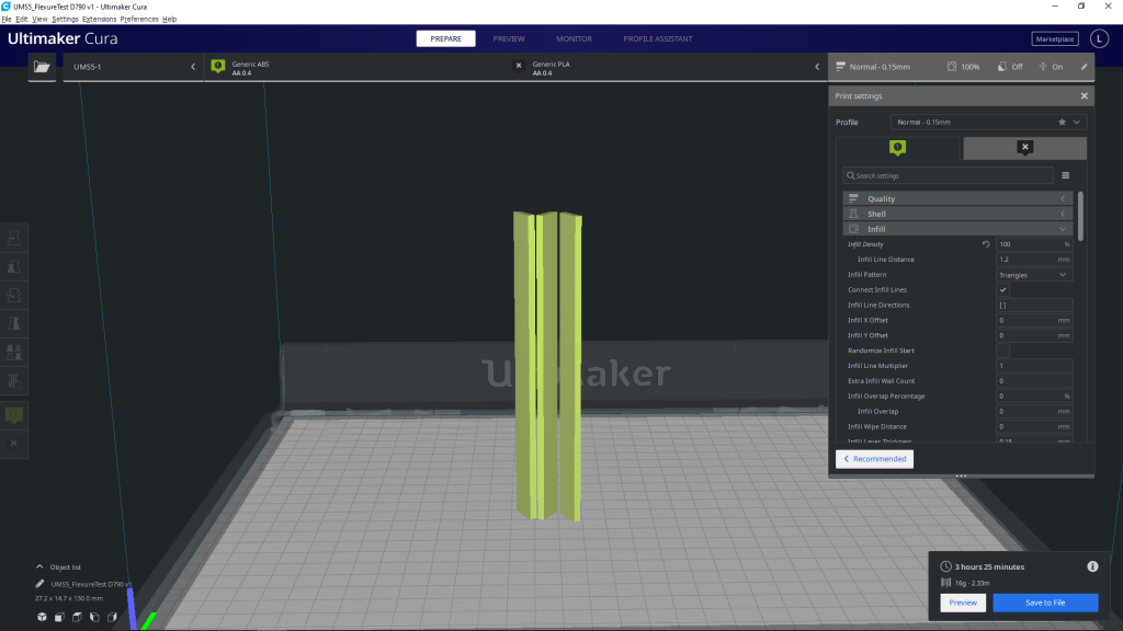
Based on this conclusion that ABS and PLA were the best materials that we had for this case study, a series of tests were conducted to find the printing temperature at which each of these materials are the strongest. This was considered for the ‘weakest orientation’ (in the Z printing direction). For ABS, the two temperatures that were tested were 255 and 265 °C. For PLA, the tested temperatures were 205, 215, and 225 °C. The testing consisted of three standard flexure prints for each temperature and material.
The prints were loaded through their centre and the maximum load before the print broke was measured. This was done to compare the Z-direction strengths of the materials and their printing temperatures. The strongest prints revealed the strongest temperature to print at. For PLA this was 205 °C, and for ABS this was 265 °C. While PLA showed a slightly higher flexure strength when compared to ABS, it was noted that ABS allowed for much larger deflections. This would make the clips less prone to snapping when fitting the part. It was therefore decided that the hubcaps will be pronted in both materials at the ideal temperature. For more information about getting strong prints at higher temperatures, check out CNC Kitchen’s video on this matter.
As for the support materials the PLA was paired with Ultimaker PVA which is a water soluble support material. The ABS was paired with Infinite Material Solution Aquasys 120. This water soluble support material has a higher temperature resistance than PVA and can be easily used with ABS. Regular PVA is not suited for use with ABS since it will soften and fail as a support material.
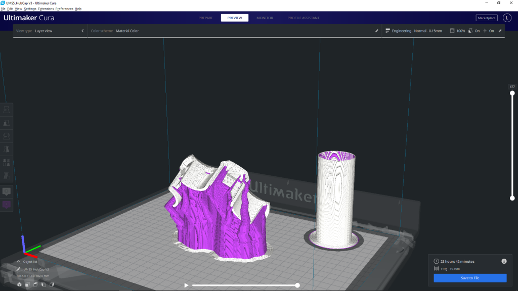
Slicing the hubcap
The slicing for the hubcap was done exclusively through Ultimaker Cura 4.8.0, and the materials to be printed were found through the Material Market add on. The hubcap was imported and positioned upright, with an angle of 30 ° from the horizontal plane.
The important settings that have been modified for this specific case study include:
- Infill density : 100%
- Support Material : Extruder 2
- Build Plate Adhesion : Brim
- Prime Tower : Enabled
Printing and Cleaning the Hubcaps
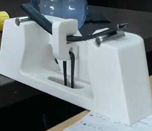
Once we had the 3D printing of the hubcaps done, they were individually immersed in water to clean them of the support structure. This process is sped up by agitating the water and causing a flow of water to continuously dissolve the soluble structure. The small pieces of support material that were stuck between the clip and the body of the hubcap were removed using a thin screwdriver.


With the final products in hand, we passed them on to the person who needed the replacement. This series of blog posts have described the overall process of measuring, designing, and then testing and 3D printing of a hubcap that has stopped being produced. This process is becoming increasingly helpful especially for replacing broken or worn down pieces of an older machine. What would you do if you had access to such 3D Printing machines and could replace a small broken part?