3D Printing Application: Hubcap Replacement – Part 1 – Measurements and Design
3D Printing is well known for its wide variety of applications. These range from hobbyists printing models of their favourite characters, to everyday functional prints for various uses, to printing farms for mass production. This blog will focus on one particular 3D printing application that may sometimes be overlooked, which is 3D printing for part replacement.
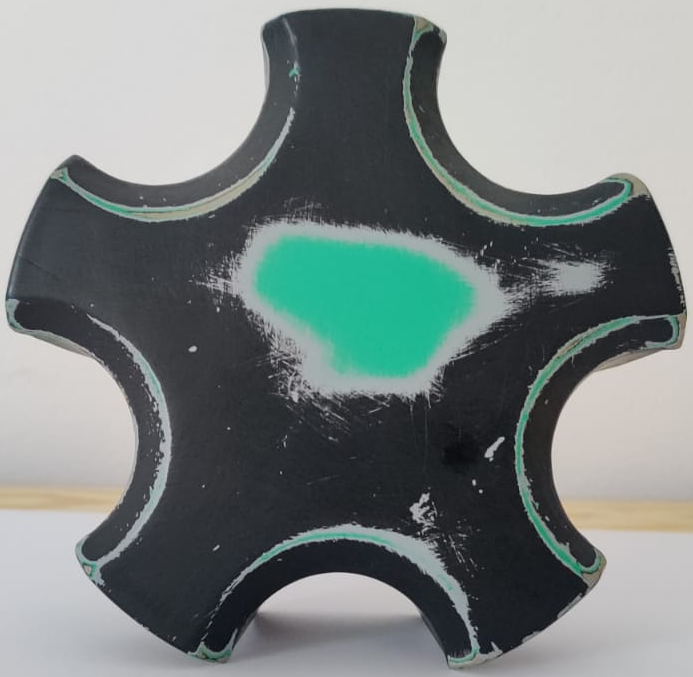
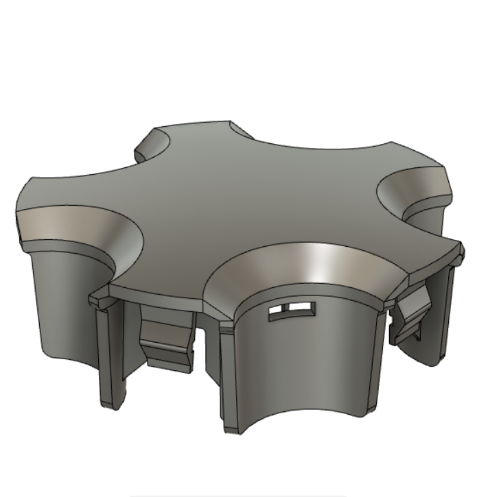
This specific case focuses on the replacement of a hubcap part from a 1991 Toyota MR2. This part happens to be a very specific and rare part, and it was unable to be found for repurchase. This makes it a perfect candidate to be replicated and designed through CAD software, and then 3D printed into a replacement.
This week, we will be detailing the process that went into printing a replacement hubcap, as well as analysing the challenges that this project presented and how these were overcome.
Measurement
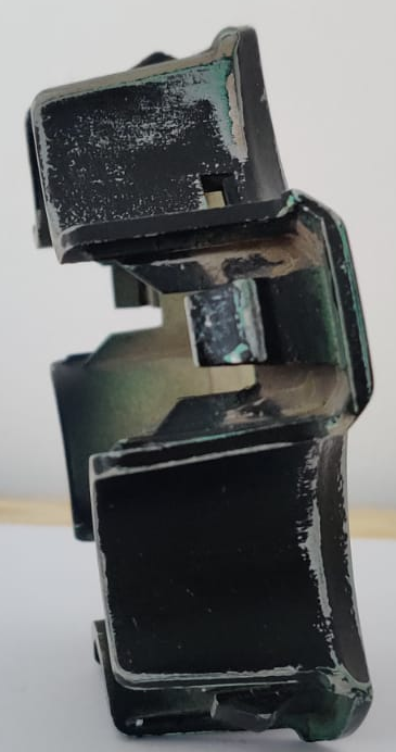
From the moment the hubcap was picked up, it was clear that some measurements were going to require some unconventional techniques to be acquired. These measurements include the overall height of the hubcap, due to it’s curved dome shape, as well as curvature of the top dome.
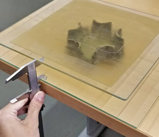
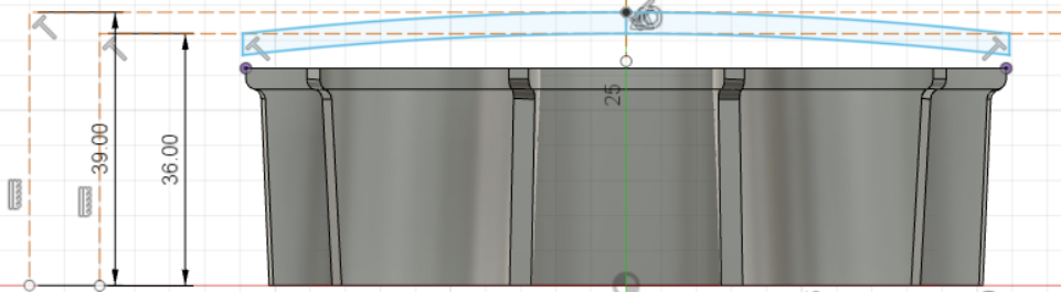
The first measurement that was taken was the height of the hubcap. After some consideration, the most reliable way of acquiring this measurement was to use two flat planes – in this case two sheets of glass – one placed under and one above the hubcap. The height between the two sheets of glass was measured using vernier calipers, at four different points along the glass. These measurements were averaged and an overall height of the hubcap was found.
Following this measurement, the curvature of the domed surface of the hubcap was calculated, rather than measured. This was done by subtracting the measurable height of one of the sides from the overall height of the part. Doing this results in the height of the domed section only. Measuring the width of the part gave the diameter of the dome.
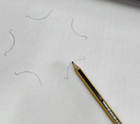
Another measurement that was troublesome at first was the curvature of the flange parts of the hubcap. The flanges follow a circular profile, and by tracing the shape of the flanges, while keeping the hub cap in position, the profile of the bottom edges was produced. By doing this, the measurements were significantly easier to acquire. The radius of the curvatures was obtained from these sketches, by using some geometric rules.
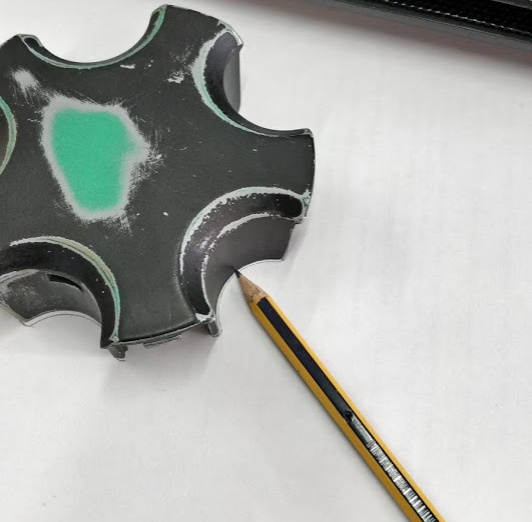
Other measurements were easier to measure with a vernier caliper. Some of these measurements are the overall length of the hubcap, the wall thicknesses, and certain feature depths. Once the sufficient dimensions had been measured, the next step was to design the 3D model.
Design
The modelling of this hubcap was done using the Autodesk Fusion 360 CAD software, making use of tools such as ‘Circular Pattern’, ‘Loft’, ‘Extrude’, and many more. It is important to note that since most of the original hubcap has a degree of rotational symmetry, only one of each feature needs to be designed fully. These features can then be replicated using the ‘Circular Pattern’ function, rather than creating five of the same feature manually.
The First Sketch
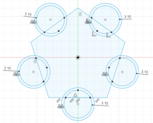
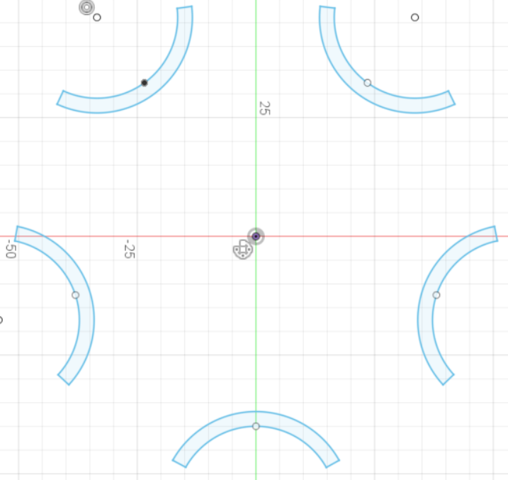
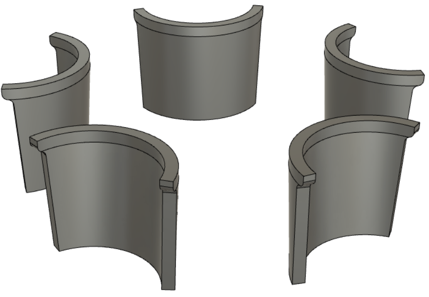
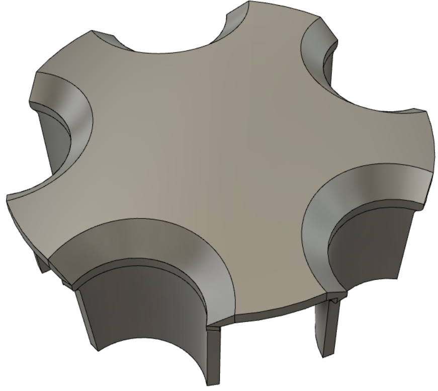
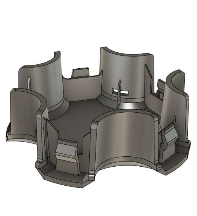
The first step to creating any CAD model is to start with a sketch. In this case, the initial sketch consists of the base profile of the rounded flanges of the hubcap. These were sketched using a pentagon as a basis, and two concentric circles on each side to represent the thickness of the flanges. After this was done, the ‘Trim’ tool was used to remove any extra lines and curves that are not a part of the actual base profile. This results in the five curved segments that represent the bottom faces of the hubcap.
Creating the Flanges
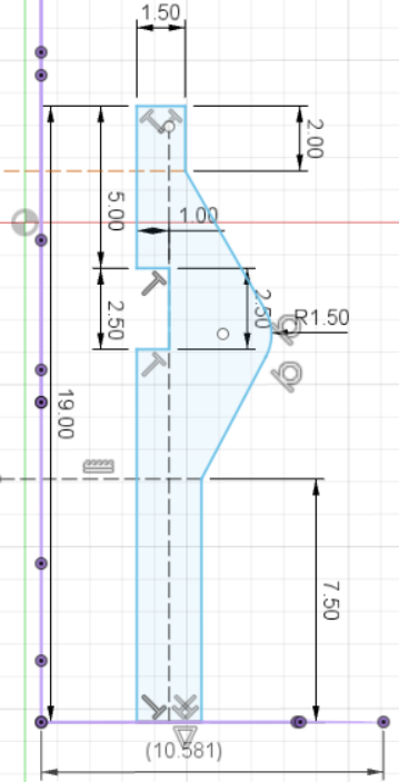
The next step is to turn the 2D sketch into 3D features. This was done by creating another plane above the previous sketch plane. The distance between these planes is the same as the measured height of the flanges. Another sketch was done on this new plane replicating the profile of the flange at the topmost section. This new sketch has a slightly larger radius and thickness, since the flange is not uniform throughout its height.
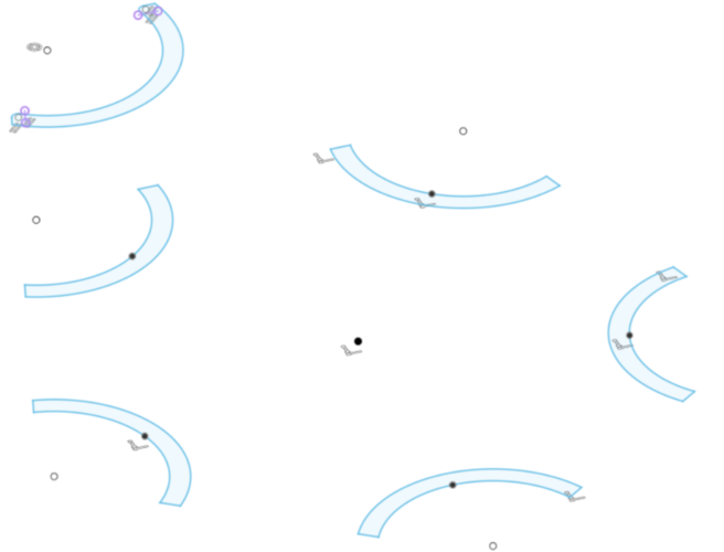
The two sketches now needed to be connected in a way to produce a 3D object. For this purpose, ‘Loft’ is the best tool to use, since it creates a path between two sketch profiles, and turns that path into a 3D body. This was done using the top sketch and it’s corresponding bottom sketch segment. Once the 3D flange was created, it was edited slightly to add a small lip and fillet to further replicate the original. Using the ‘Circular Pattern’ tool, this body was replicated into four other flanges.
Adding the Dome
Following the creation of the flanges, the domed top surface had to be designed and added. The measurements taken previously were replicated into a sketch, and the dome was created using the ‘Revolve’ tool. To cut the slots in the dome as necessary, a circular sketch was created and cut from the dome. This was once again replicated by using the ‘Circular Pattern’ tool.
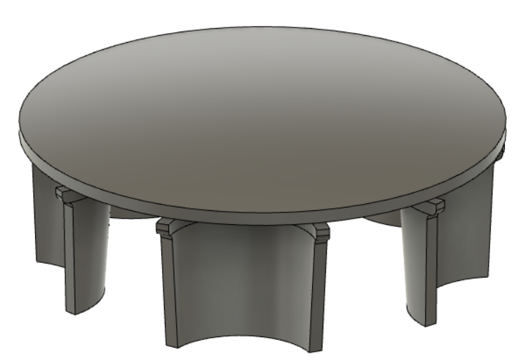
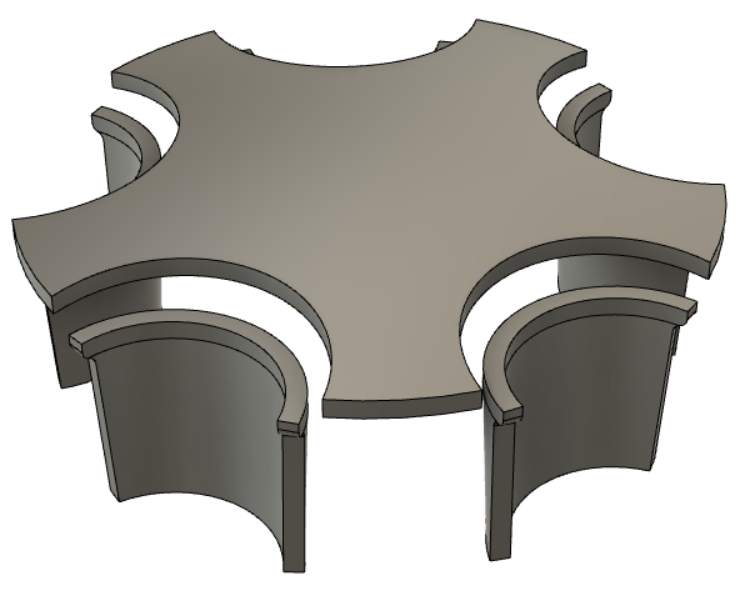
Connecting the Dome and Flanges
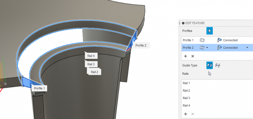
This part of the modelling was the most challenging, since the bevel between the dome and the flanges had a radius and angle that constantly changed throughout its length. Eventually this was done by using the ‘Loft’ tool again, but this time, making use of the rails feature of ‘Loft’. This allows two separate profiles to be connected through a very specific path, which causes the shape in between the profiles to conform to the rails. Once this feature was created, the ‘Circular Pattern’ tool was used once more to replicate it for the rest of the hubcap.
The Clips and other small features
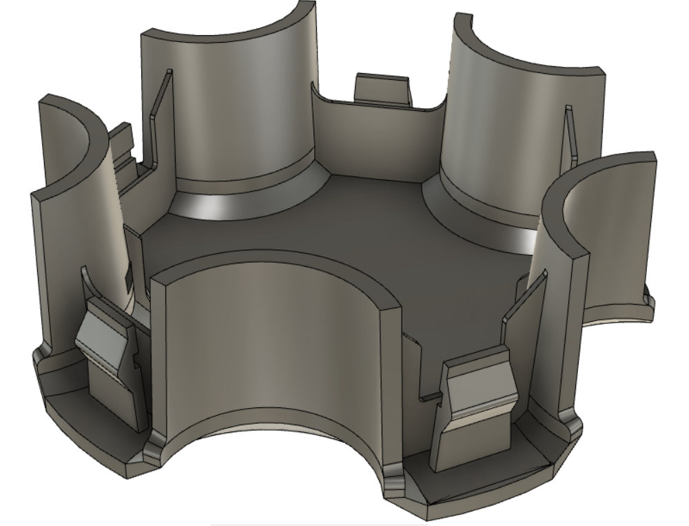
With the main body of the hubcap complete, the only few features left to design were the clips, webs, holes and other small intricacies. Most of these were easily designed using simple sketches and extrusions. The clips however took some more thought, as they had to be implemented as accurately as possible. After a thorough sketch of the clip, it was extruded into a 3D feature, and replicated through the ‘Circular Pattern’.
Finishing off the 3D Model
Once all the features and intricacies were designed and modelled, it was time to finish off the model and prepare it for the final design. This was done by adding fillets to some edges to give the model a smoother feel. It is important to note that fillets also give a 3D printed part some additional strength and reduces stress concentrations at any particular corner.
With this done, the model was finalised and ready to be sliced and printed! Stay tuned for part 2 of this blog post to find out how we printed test parts, fitted and selected a material for the final part!