3D Printing Nylon functional parts: E-bike Horn Mount
Commuting by cycling has many advantages when compared to using automobiles. These include, a reduced carbon footprint and not getting stuck in traffic whilst also being good physical exercise. Nonetheless cycling as a mode of transport can also have several potential downsides, including hills, the need of a shower after a commute and increased vulnerability on the road where proper infrastructure is not present. The first two problems can be easily offset by owning an E-bike which makes commuting a breeze. However for the latter problem a more radical solution might be needed. In this article we will see how I produced a bracket for a horn by 3D printing Nylon parts.
Why mount a horn on a bike?

Having had my fair share of close calls on my daily commute, I decided that I needed a better way to alert drivers of my presence on the road. This is especially true when it comes to junctions and roundabouts where a cyclist can easily not be seen. In these cases a bicycle bell or shouting at the top of your voice will not be enough. Furthermore road users tend to react very quickly to the sound of a horn as opposed to other warning sounds.
While off the shelf ‘bicycle horns’ do exist, they can be costly, not loud enough or not make the appropriate sound. Most of all however, they are nowhere near as fun as building one from a recycled horn, 3D printed Nylon parts and several design attempts.
Before you try this, check if this is legal in your area and also be considerate of other road users. It should be noted that the aim of a horn is not to get people out of your way. Only use a horn as a last resort to alert other road users in case of an impending collision.
List of parts
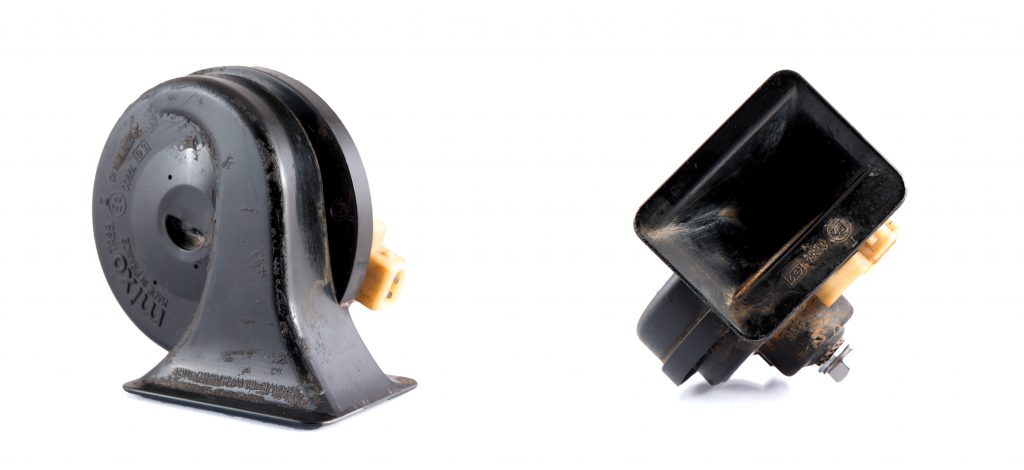
Horn: I salvaged the horn for this project from a mk3 Ford Fiesta. One can easily find a horn for next to nothing from a car recycling plant.
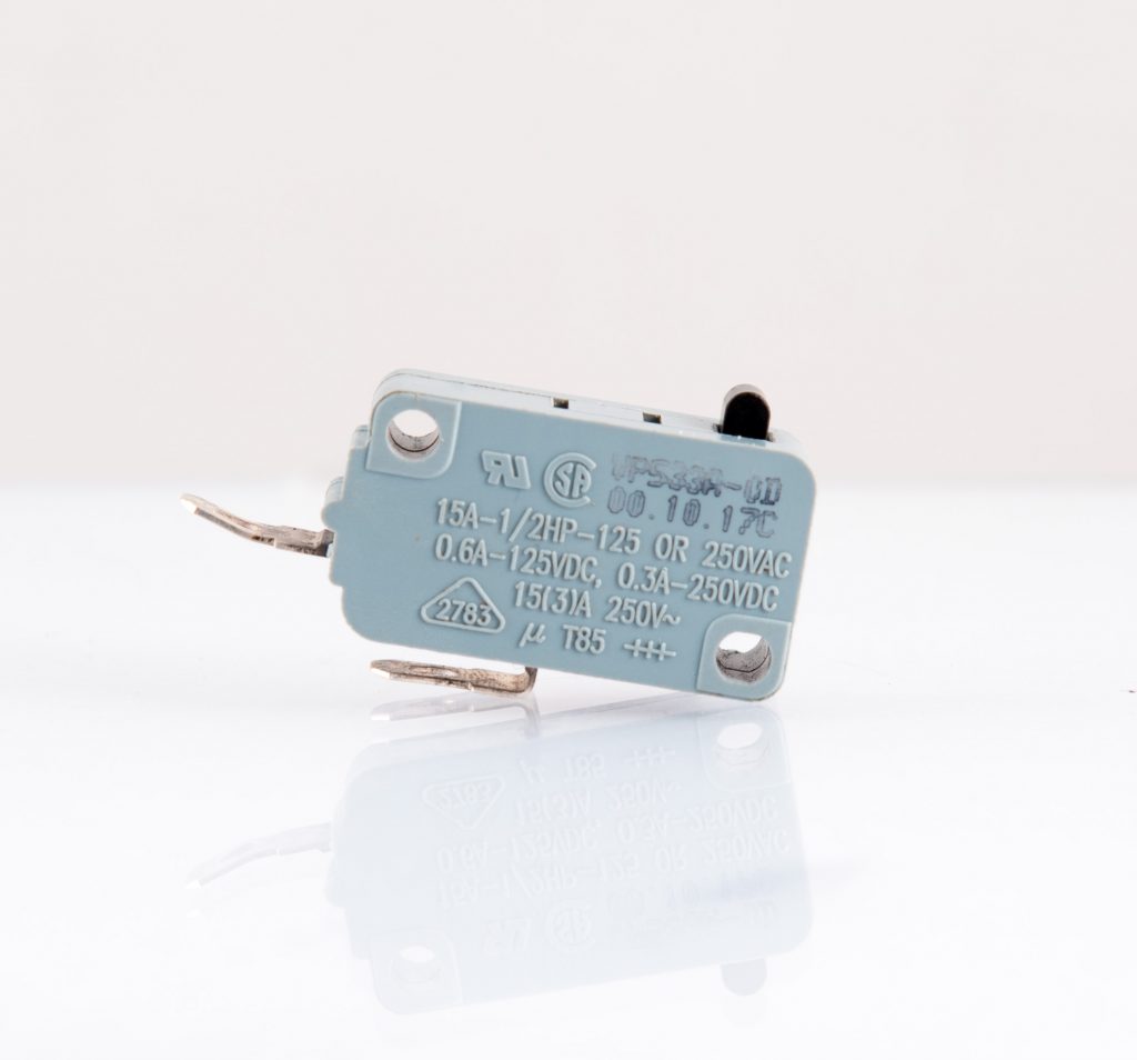
- Push switch: A push switch salvaged from a fridge will be used. The switch has a short travel and is able to easily cope with the current load of the horn.
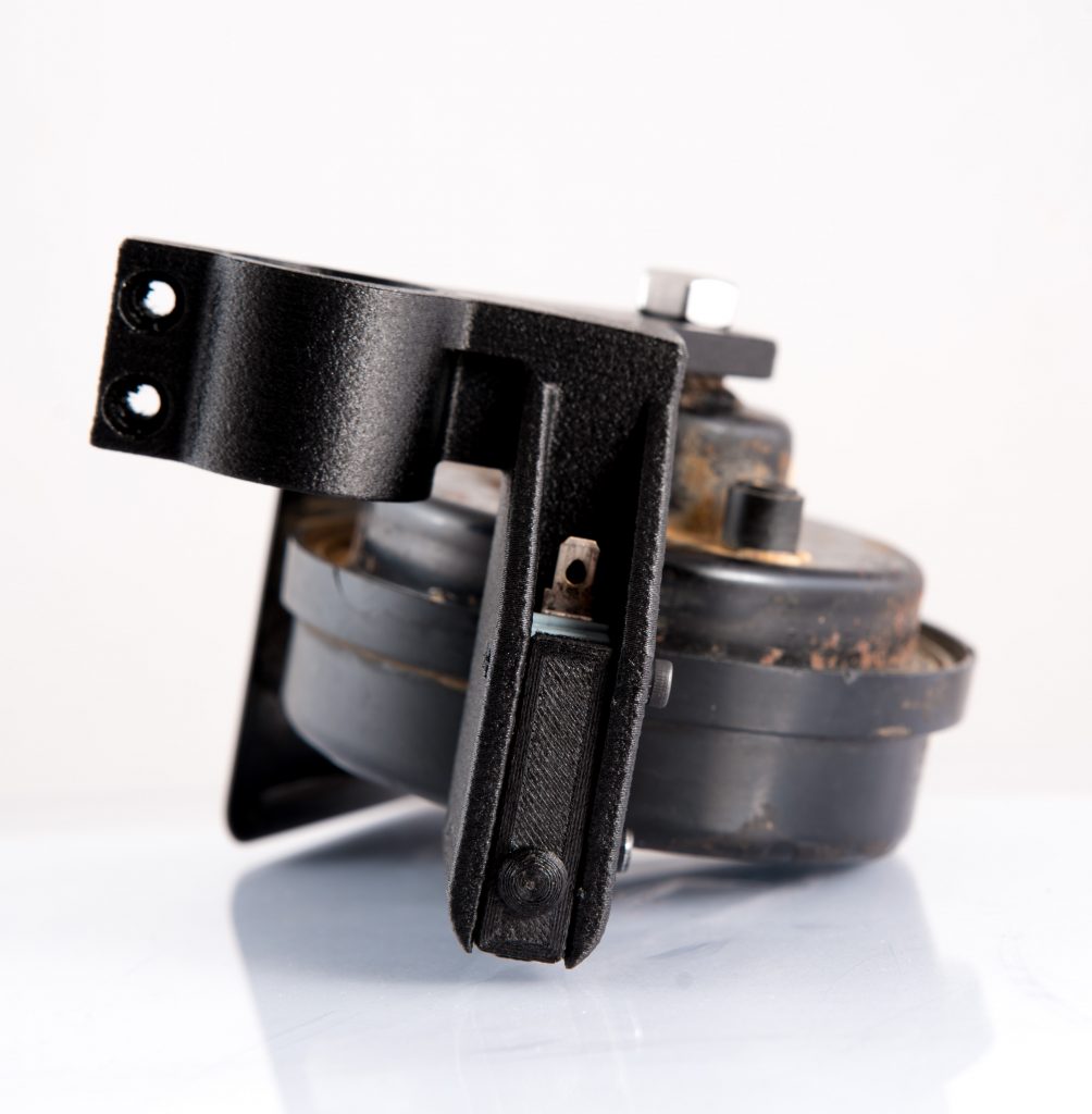
- Horn bracket: This part needs to hold the horn in place and will be 3D printed. It needs to be strong enough to cope with daily use on smooth and bumpy roads.
- Power source: 3 18650 3.7 V lithium ion batteries in parallel will be used as the power source. These cells are powerful enough to supply the 12 V, 2.5 A needed by the horn. This power source already exists and serves to power the bicycle lights.
- E-bike/bike: well duh!
Design and placement
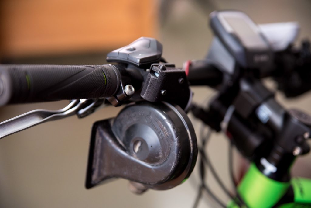
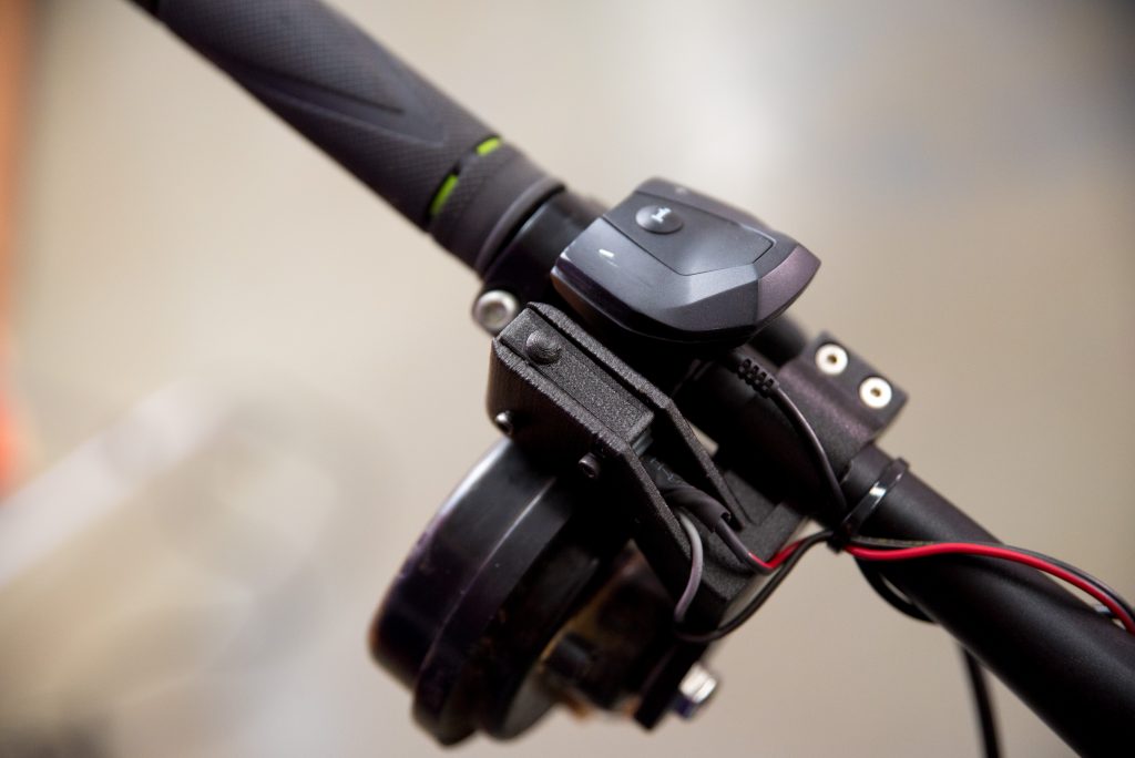
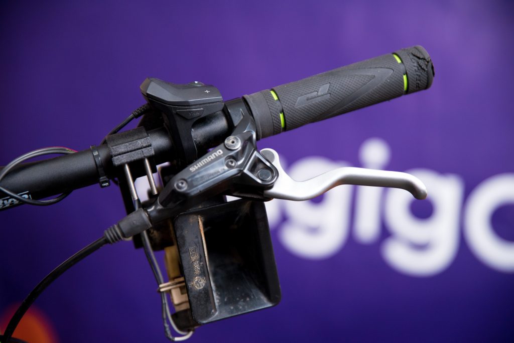
Before any design can start, I had to decide where to mount the horn on the bike. At first I wanted to mount the horn to the head tube or behind it, underneath the top tube. However due to the limited mounting options, the easiest route was to mount it to the steering tube. This has the several advantages since I would design the mounting bracket and actuator in one bracket. The power source is also already mounted on the steering tube, thus wiring the switch and horn unit is also simpler.
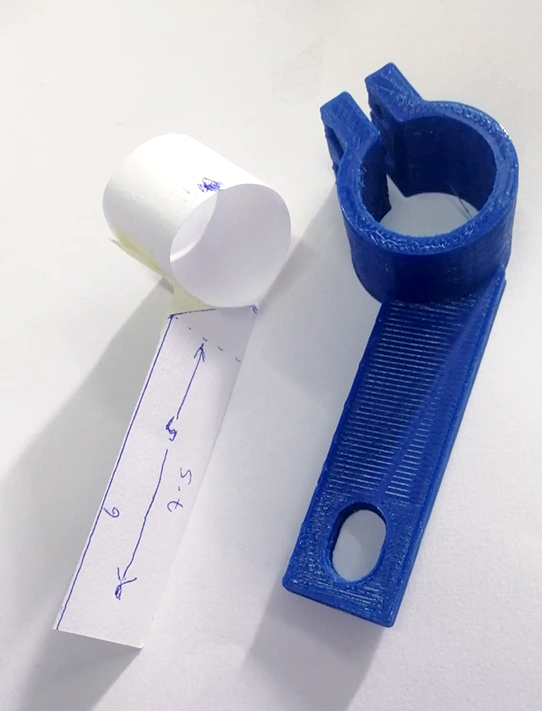
I started by doing some measurements and cutting out a quick paper template (figure 1). After some adjustments to the paper template, I transferred the measurements to Fusion360 (figure 2). In a few minutes I designed and printed a prototype in PLA to check for fit, before 3D Printing Nylon parts.
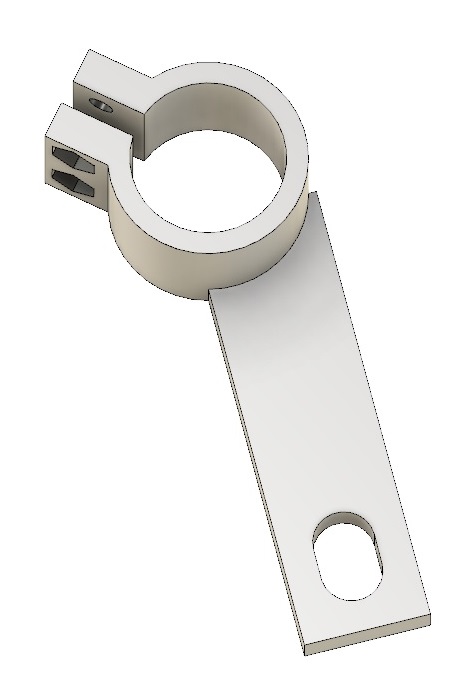
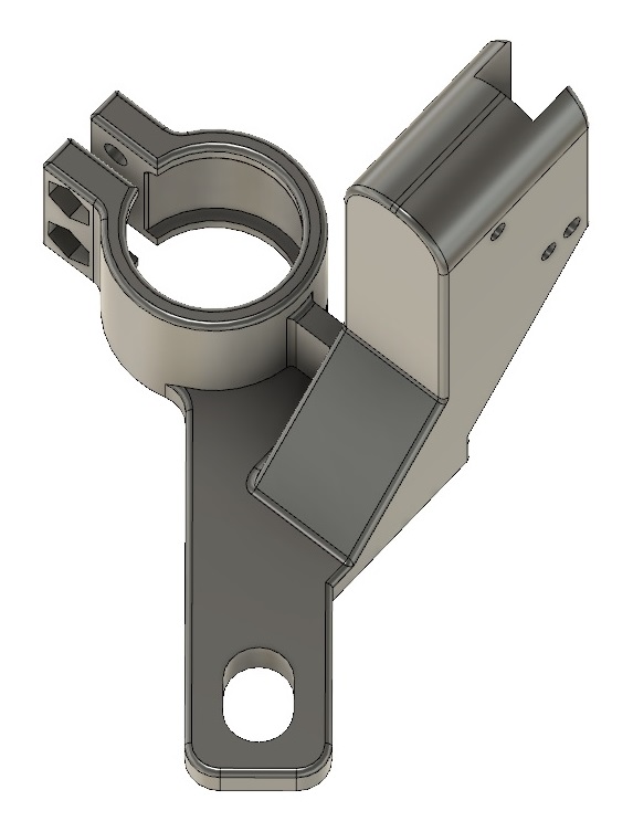
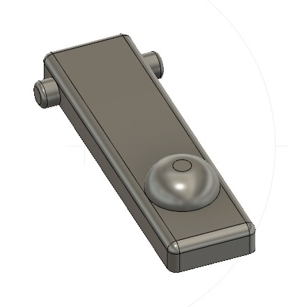
After several iterations and several fillets I ended up with a part that I was quite happy with (figure 3). I added a cavity to house a printed rubber ring to fit in between the part and the steering wheel. The mount will be secured using 2 M5 bolts and nuts, while the switch will be kept in place using its existing holes. Two holes were added so that M3 bolts can be threaded through and secure the switch. A ring to be printed out in a flexible material (figure 4) was added so as to dampen vibrations, prevent the steering tube from being scratched with the printed part, whilst also resisting rotation of the whole assembly. Finally I also added a flap to enable me to push on the switch more easily (figure 5). This flap will fit inside two holes present on the assembly which enable it to rotate.
Material selection
Polymaker PolyLite PLA was used to print prototype parts. PLA is our go to material for the production of prototypes and functional parts which don’t require a lot of flexural strength. While PLA prints can be appreciably strong, PLA is also quite brittle and thus susceptible to fail without warning. Most engineering materials such as PC, Nylon or ASA would probably be up to the task. However since parts of the bike have a rough matte black finish, a carbon fiber composite would give a very similar finish when printed.
Matterhackers Nylon X is is a carbon fiber reinforced nylon filament. The addition of carbon fibers to nylon results in a tough filament with stiffness, impact resistance, and high tensile strength. Carbon fiber reinforcment also reduces shrinkage during printing which helps reduce warping and improves dimensional stability.
Magigoo PA enables one to 3D print nylon and reinforced nylon materials on a multitude of printers with a heated bed capable of reaching around 80 °C. The printing temperatures will however depend on the filament and printer combination, the optimum temperature can be found by following the method described in a previous blog post.
The shim was printed using DSM Arnitel ID 2045 with Magigoo Flex as an adhesive on an Ultimaker S5.
3D Printing Nylon X and Assembly
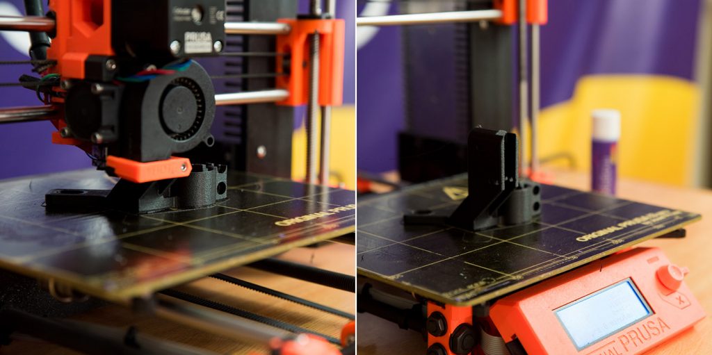
The bracket and the switch flap were printed on a Prusa i3 MK2s with the following printing settings. The models were sliced on Prusa slicer using the Taulman Bridge system preset as a starting point :
- Build-plate temperature: 90 °C – this should
- Nozzle Temperature: 265 °C
- Layer Height: 0.2 mm
- Shells: 4
- Infill 50%, gyroid
- Cooling off except for bridges
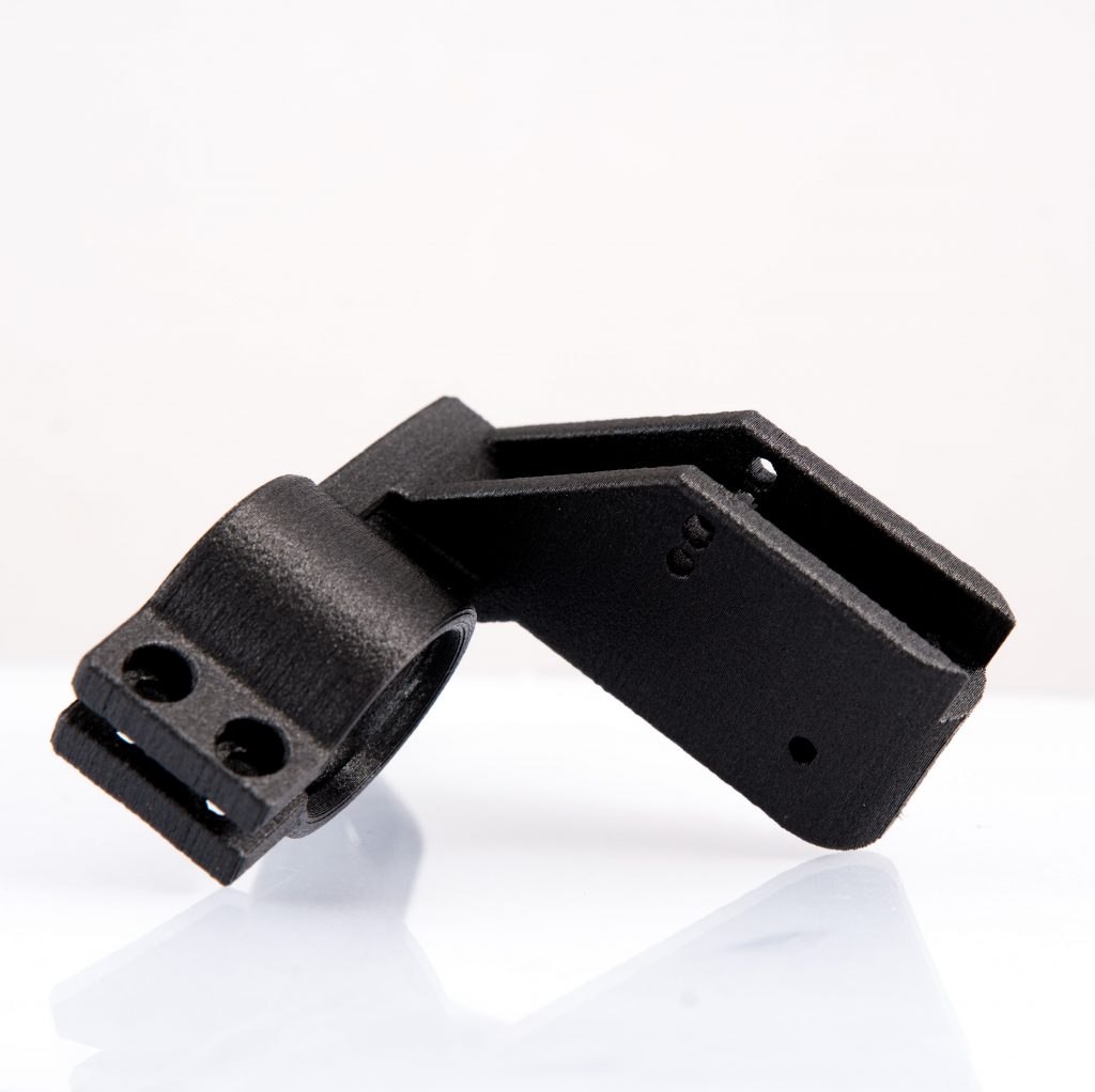
Once finished, I mounted the parts on the bicycle, wired and soldered everything in place and was ready to go! Here are some images of the mount in place on the bike!
Watch out for more interesting 3D printing projects in the future! Do you have any questions on this article or cool project you would like to see. Let us know!