Design Tips – How to design for 3D Printing
Finding a model to 3D print is fairly easy nowadays, with there being over 2 million models over on Thingiverse. This however does not mean that you will find anything you need on that database. This is especially the case if one requires a custom print, with a specific design. The main method of producing a model is to design it through CAD software like Autodesk Fusion. This blog post will address the issues of design for 3D printing and how to go around these issues.
The tips given in this blog post are split into two sections. The first will describe some general tips on designing models for 3D printing. The second section is about designing models for 3D printing assemblies in one go.
General Tips on Design for 3D Printing
The following tips are all about how to design certain features of a model, to ensure maximum printability and to reduce the chance of print failure. They are not 100% must follow guidelines, however, following them will increase the chance of a successful print.
Support Structure
Support Structure is a necessary evil in most prints, and cannot be avoided. That being said, it can be thoroughly reduced through a better design of the part.
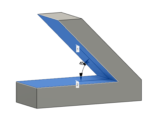
Typically for most materials, the support structure is needed for overhangs that have an angle greater than 45°. Generally, if the angle is greater than 45°, the deposited material already has enough support from the layer below it, and will not require any extra support structures.
Another detail regarding support structure is to keep in mind the difficulty of removal of the said support structure. Especially when it comes to small holes or hidden sections, the support structure can be very difficult to remove. This should be considered when designing a part or component. A solution for this would be to use soluble support material if possible. However, when this is not possible, the hidden or hard to remove support structure should be reduced.
Small Holes and Small Pins
For most parts that have to be assembled into a larger assembly, there will almost certainly be a few holes or a few pins. Designing these pins and holes is crucial to the final product, as with a hole too large or too small, the part will not mate properly.
The main issue that occurs when printing a hole is typically when the hole diameter is too small. This depends on the 3D printer that is being used, as more advanced and precise printers have the capability to 3D print holes more accurately, and with smaller diameters. The same problem also applies to the 3D printing of pins. The better and more accurate the printer, the smaller the printable diameter will be.
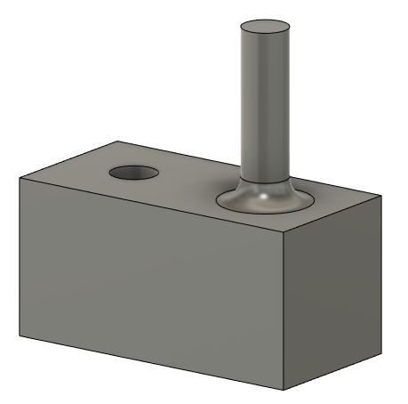
Another issue that occurs when 3D printing a small pin is that it turns out very brittle and can be snapped easily. Adding a fillet to the bottom of the pin will increase the strength of the base of the pin. Another solution is to design the part to be 3D printed in an orientation that results in the pin being horizontal.
Knowing the capabilities of your 3D printer is important when it comes to designing a part, so make sure that you perform some tests on it to find out what it can and cannot do!
Gaps
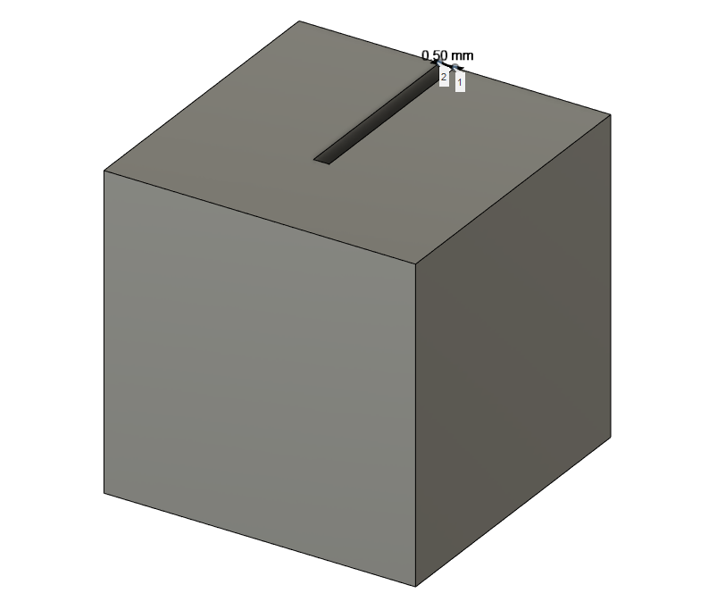
Similarly to the Holes and Pins, there might arise a need to 3D print a gap or slot in a part. Once again, different printers allow for different capabilities. Typically, for advanced printers like the Ultimaker machines, the minimum distance between two faces that can be printed is around 0.5 mm, and this increases with less high-end 3D printers.
Slots or gaps designed smaller than 0.5 mm in width have a high chance of not getting 3D printed properly. What would happen is that the walls are too close together, and might fuse together while the material is still hot.
Finding the minimum 3D printable gap is important especially when designing parts that clip into each other, or parts that should fit together using a clip or hook.
Wall Thickness
When creating some sort of housing for a component, it is important to have good, sturdy walls, while also reducing the material used. For features like walls and sections, depending on the material and 3D printer, one could design the optimal wall thickness to ensure minimum material usage, while also keeping the wall sturdy enough.
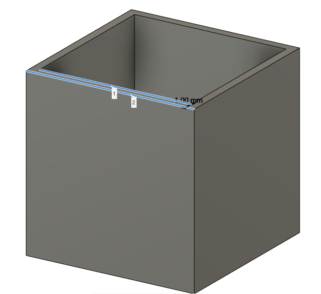
Typically, a 1 mm thick wall is easily printable on all machines, however, this depends on the material that is going to be used. The design for 3D printing walls should always take into consideration the specific use of said walls. If the wall is load-bearing, a larger thickness might be beneficial.
Tips on designing for 3D Printing Assemblies
The previous tips were in reference to the design for 3D printing individual parts. This section will give some tips on the design for 3D printing of whole assemblies, in one print. These are assemblies that can be 3D printed whole, with no assembly required post-printing. Naturally, all of the above tips still very much apply to this section, especially the support structure tips.
Number of Components
When it comes to 3D printing an assembly, there will always be multiple components, and typically some of them will be in motion relative to each other. While there may be some moving parts, there will also be parts that are static relative to each other. These are parts that can be statically mated, which means they can essentially be fused into one part during the design of the model.
It is important to reduce the number of components in a 3D printed assembly as much as possible. The fewer components there are, the fewer mating complications there will be, and a higher chance of a successful 3D print.
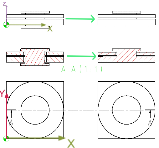
As can be seen in the image above, the pin mechanism on the left consists of 3 parts; the pin, the top plate, and the bottom plate. The top plate and the bottom plate are the only two that need to be able to rotate. With this in mind, the pin can be fused to the bottom plate, and be printed as one component. This enables the same mechanism to work with fewer individual components.
Gaps between Components
The previously mentioned tip about the gaps in components can also be applied to the gaps between components. Most commonly, these gaps will be seen in pins-and-holes pairs, as well as cylinders-and-bores pairs.
Such components in an assembly typically require a degree of motion. This may be either to move in and out of each other or to rotate on their common axis. Either way, the gap should be clear of any support material or fused material. For this reason, on high-end printers like the Ultimaker, this gap should be no less than 0.5 mm. This depends on how tight fit the cylinder needs to be in the bore. The larger that gap, the easier they will move, but the looser the tolerance will be. The smaller the gap, the tighter the tolerance but it will also be more difficult for the parts to move. The gap you should design into the assembly should fit the purpose of the assembly itself.
Overall, one should always keep in mind two things when designing a model for 3D printing. Firstly, the capabilities of the 3D printer that is going to be used should always be considered. Secondly, the main purpose of the model and dimensional tolerances should be taken note of and designed accordingly.
If you enjoyed this blog post, be sure to check out one of our previous blog post series where a Hubcap replacement was designed and 3D printed.