Best 3D printing settings for less warping
This is part 3 of our 4 part blog series. This series is about warping and how to optimise your 3D printer’s bed temperature and increase your first layer adhesion to reduce this effect. In part 3, our chemist Jean Paul Formosa, will discuss how to determine the best 3D printing settings for minimum warping.
How to determine the best 3D printing settings for minimal wapring
This process of finding the best 3D printing settings in terms of build-plate temperature is relatively simple but often overlooked. One needs to print a test print specifically designed to assess the warping behaviour at different temperatures. This print is preferably small in order to minimise the wastage of filament and also to save time, however also needs to be a good indicator of adhesive performance. A print with a wide base and a low z-height is not an ideal indicator of adhesive performance, on the contrary prints with narrow bases such as wedges (Figure 1 – downloadable here) and prints with sharp corners are usually more prone to warp and more ideal for assessment of adhesive performance. Such prints can be easily found online on sites such as Thingiverse – (Figure 2, Figure 3).


Tools and Materials:
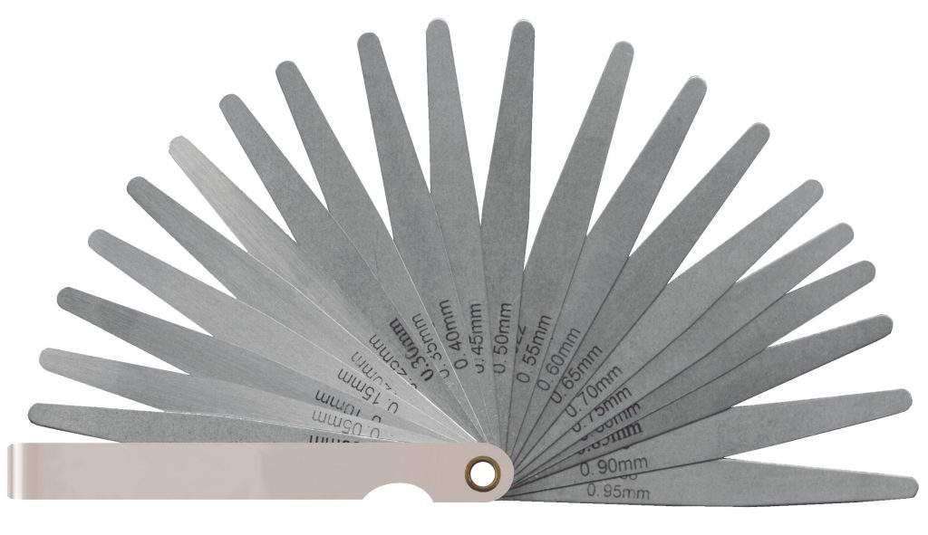
Apart from a well-functioning and calibrated 3D printer and a 3D model for testing, one would also need some way to measure the amount of warp on a print. This can be done by visual comparison but can also be more accurately done using a feeler or slip gauge in order to determine the amount of warp quantitatively (Figure 4). The calibration of 3D printer bed temperatures will be tackled in a future article.
Method:
1. One can start the test from a recommended build plate temperature setting, either such as those suggested by the filament manufacturer or from other reliable sources. Alternatively one can use the table below as a rough guide for the optimum printing temperature for different materials and utilising the different Magigoo adhesives.
Material | Magigoo Adhesive | Build-plate temperature |
| PLA | Magigoo® | 50-70 °C |
| PET-G | Magigoo® | 60-90 °C |
| PET | Magigoo® | 60-90 °C |
| CARBON FILLED PET | Magigoo® | 60-90 °C |
| CPE | Magigoo® | 60-90 °C |
| ABS | Magigoo® | 80-110 °C |
| HIPS | Magigoo® | 80-110 °C |
| NYLON | Magigoo® PA | 60-100 °C |
| GLASS FILLED NYLON | Magigoo® PA | 60-100 °C |
| CARBON FILLED NYLON | Magigoo® PA | 60-100 °C |
| PP | Magigoo® PP | 60-90 °C |
| GLASS FILLED PP | Magigoo® PPGF | 70-100 °C |
| PC | Magigoo® PC | 90-120 °C |
| TPU/TPC | Magigoo® Flex | 60-100°C |
| PEEK | Magigoo® HT | 150 °C |
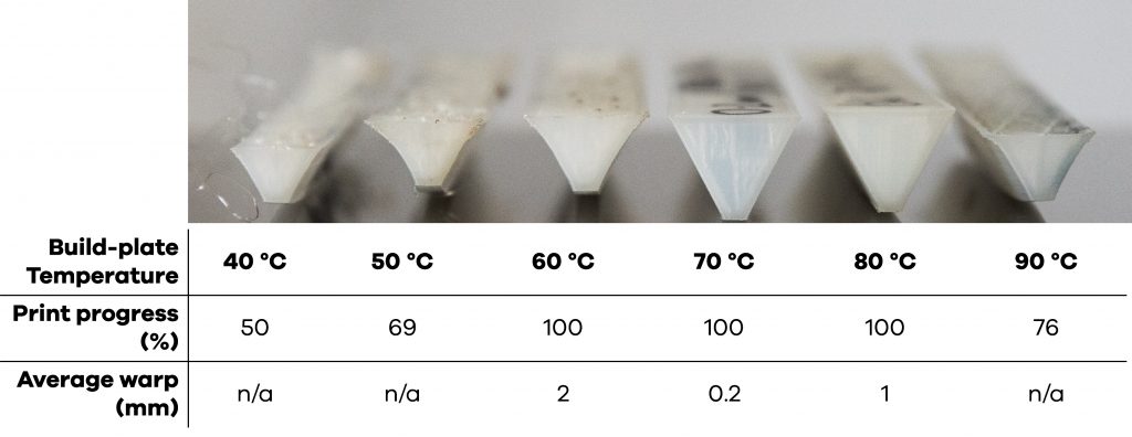
2. Once the temperature at which testing will start is determined, let’s call this T0, one can print a test print at this temperature, wait for it to finish (if it finishes) and measure the warp at each end or corner of the print. If the print does not succeed, the point at which the print became completely detached from the build plate can be used as a data point (Figure 5).
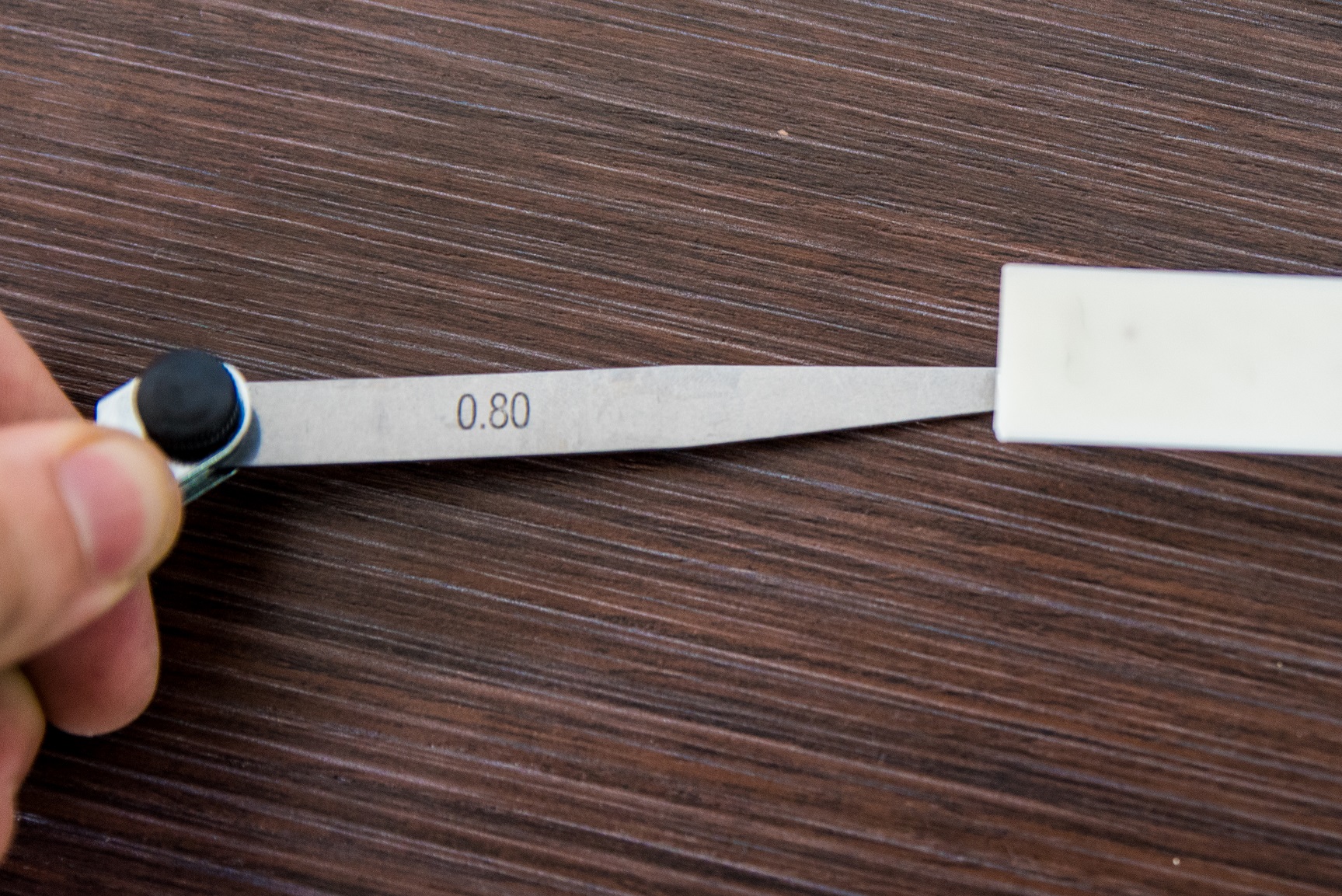 | 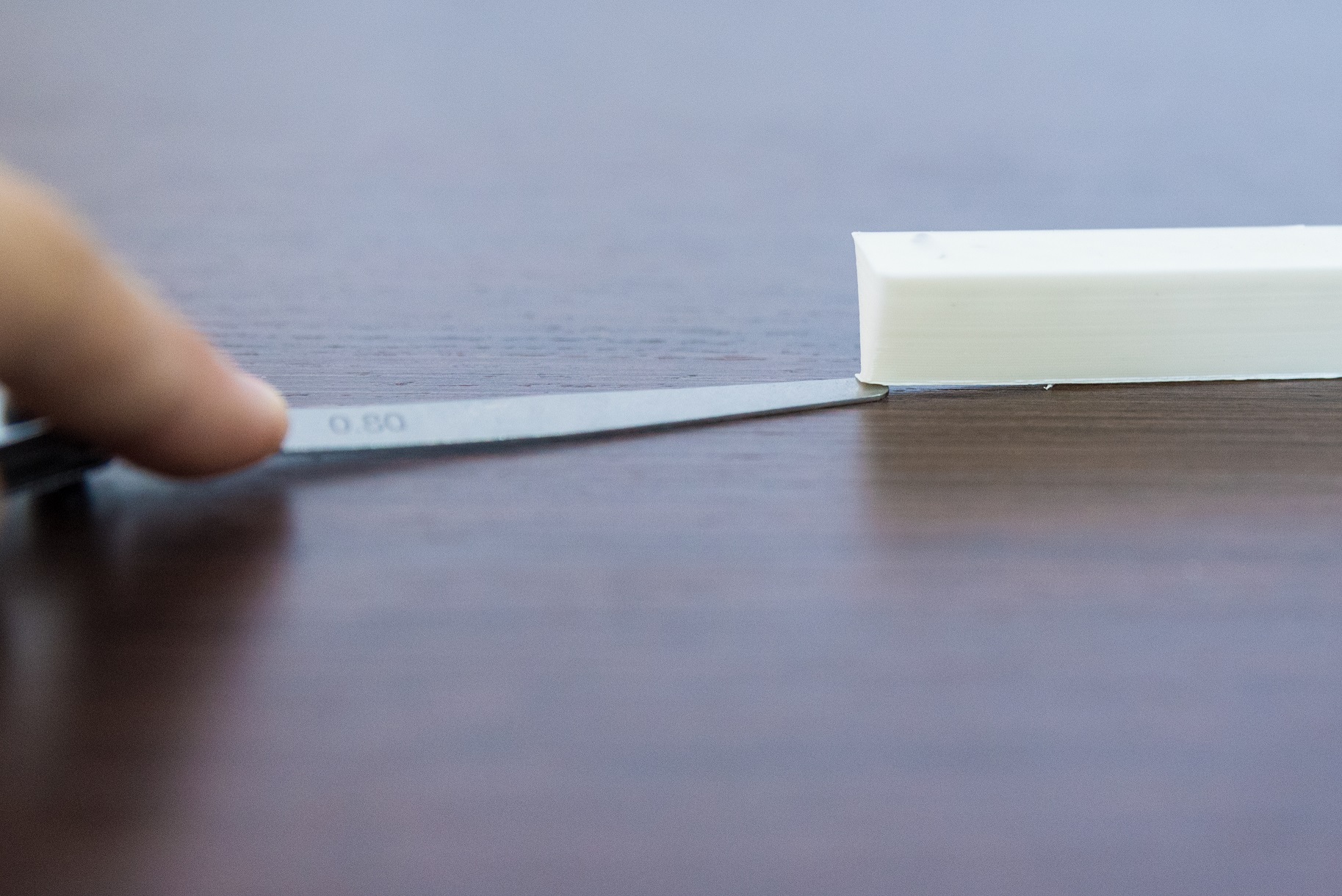 |
| Figure 5: Measuring the warp on the edge of the wedge print using a feeler gauge |
3. After this, one can perform the same test using the same settings at different build plate temperatures in steps of 10 °C above T0. At a certain stage of printing, the amount of warping of the test print at a higher temperature will be visibly more.
4. If the warp continues increasing on the next increment for the build-plate temperature, one can safely assume that further increasing the temperature beyond that point will cause the print to warp even more. Thus one can stop increasing the build-plate temperature.
5. The test is continued starting from 10 °C below T0 and decreasing in steps of 10 °C. Again, at a certain stage the warp will start increasing as the test print is performed at lower build-plate temperatures. At this point one can stop testing the effect of further reduction in build-plate temperature.
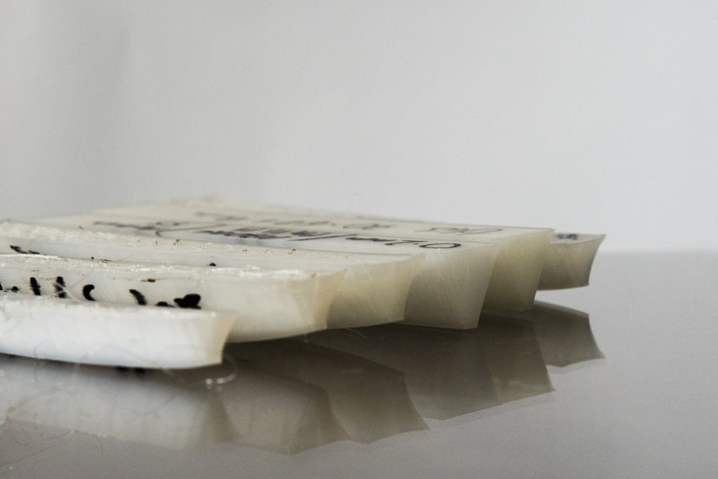
6. Once all the tests are performed, the temperature at which the print with the least warp can be determined. That is your ideal build-plate temperature for the adhesive, material and printer combination (Figure 7).
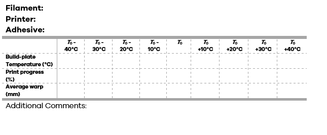
Warping chart template
A blank template for noting and keeping record of the optimum build-plate temperature can be seen below and downloaded from here.
If you missed the previous parts of this blog post you can find them here: Part one, Part two. Look out for part four next week.